The Northeast kingdom railroad


One Evening Caboose Project
Are you looking for an interesting one night project for your layout? Perhaps something a little different than the usual structure or freight car kit? Here is one that is fun to do and will add a little animation to your layout, a rear end warning flasher for your caboose. I easily completed this project in one evening during the summer while watching a baseball game on TV.
Recently I was watching a prototype railroading DVD that showed a Canadian Pacific train in Vermont during the early 1990s sporting a flashing red warning beacon on the caboose (yes, the CP was still using a caboose in the 1990s, at least in Vermont). It looked pretty neat as the train headed up the mainline out of sight. I thought this would be a neat detail to add for my HO layout and would be an eye catcher during open houses.
First I needed to find something that would supply the flashing beacon. A trip to the hobby shop was successful as I found a Miniatronics flashing circuit with a red LED, part #100-011-01. This unit is specifically made to be used in the situation I wanted. The circuit board will easily fit inside an HO or N scale caboose body and the LED is shaped with a round end that will fit into a hole drilled into your caboose end.
Now for those more electrically inclined, I’m sure building your own circuit with an LED is a pretty easy task. But I’m not really that familiar with electronics, so having the circuit ready to install helped me keep this as a one night project.
With my flashing circuit taken care of I needed a way to power it. The circuit can use between 9 and 14 volts of AC or DC. So one option would be to use a 9 volt battery installed in the caboose. You would want some way to turn the power off and on if you go this route and Miniatronics does supply a mini switch that you could mount somewhere on the caboose. Having DCC on my layout, I decided it would be easy enough to pick up power from the track making use of the metal wheels on my caboose. So this meant I needed to find something to draw power off of the caboose wheels.
The hobby shop again had just the item I needed, Tomar contact wipers, part #H-825. This is a kit that can be used for a variety of electrical pickup purposes, such as locomotives and tenders. But it had everything I needed to get power from my caboose trucks and to the circuit board.
March/April 2009
MER Local
This is an article I wrote for the MER Local. It is a one evening caboose project to add a flashing beacon to the end of the caboose. It was published in the March/April 2009 edition.
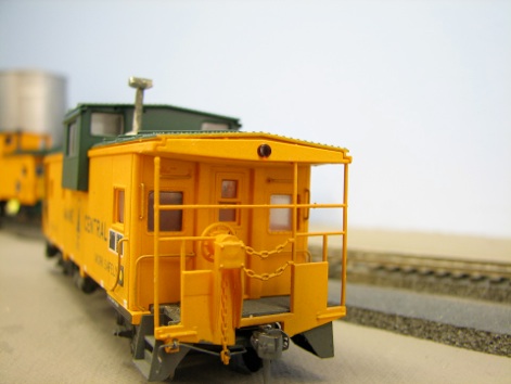
Next I needed to decide which caboose would work best to install the flashing beacon. I wanted to mount the flashing beacon on the end of the caboose near the roof similar to what I saw on the DVD. I found that many of my caboose models I have did not have end fascia to easily support mounting the LED. These models simply had the roof edge on the end. But the recent Atlas HO standard and wide cupola models do have this fascia piece and space behind it mount the LED. So I looked over my Maine Central Atlas caboose fleet and selected a wide cupola model for the project. For your project, make sure your caboose has an area to mount the visible portion of the LED while keeping the rest if it hidden.
Having the flashing circuit and contact kit procured I was now ready to start work on the project. I gathered the parts I purchased, the caboose model and my toolbox (including my soldering iron) and got set up in front of the TV as the first pitch of the game was thrown.
I started by separating the body shell from the underframe. If using the Atlas model, be careful here to pull the ladder and end rail casting out of the mounting holes in the underframe before pulling the body shell up off the underframe. Next I drilled a 5/16” hole centered in the end fascia for the round portion of the LED. Behind the fascia the rest of the LED can be hidden, although it is slightly longer than the space available. To make room I drilled 3 holes next to each other in the top of the rear wall above the end door and cut out the area between them to fit the rectangular portion of the LED. I pushed the LED from inside the caboose through the larger wall hole and into the end fascia. I used a drop of CA glue to hold the LED in place. The LED is pretty well hidden but I also added a piece of .005” styrene sheet to cover the complete rear overhang area, hiding the LED underneath. I painted the styrene harvest gold to match the caboose color, although black would probably also work.
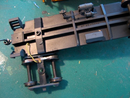
With the LED installed, I turned my attention to the electrical contacts on the wheels. The Tomar kit comes with a thin phosphorous bronze sheet that you cut as needed. Using a new blade in my Xacto knife I cut two thin strips of the material to mount on the trucks and rub the treads of two wheels on each truck. The kit also comes with thin connection wire and I soldered short sections of wire to the center of each strip. Next I put a dab of Liquid Nails on the trucks behind the sideframes. The glue itself is not strong enough for a permanent installation but it holds the strips in place for the next step. The Tomar kit includes small screws for mounting purposes. The instructions really call for screwing a section of printed circuit board in place but I found I could do the install without the PC board. I drilled a hole for the screws right next to the already attached contact strips and inserted the screws. The result is that the screw head covers part of the contact strip securely holding it in place. This glue and screw combination has held up well in use on the layout.

I routed the thin wire from the contact strips through a hole I drilled on each end of the underframe next to the floor weight. These wires get soldered to the leads from the circuit board. I first shortened the wires on the circuit board to help reduce the amount of wiring inside the caboose body. Make sure the thin contact wires are a little loose so the trucks can turn freely.
With the wire from the contacts attached and the LED installed, the construction work is complete. I used double sided foam tape to hold the circuit board on top of the floor weight. Before reassembling the caboose, it is a good idea to test out the circuit and contacts to make sure everything is working OK. I put the caboose on the track and the flasher started working. I rolled the caboose a little and noticed that it it did not roll too easily. Looking at the contact wipers, I noticed one was a little tighter against the wheel tread than the others. I used pliers to gently bend that side of the contact strip away from the wheel tread to take some of the pressure off of the wheel where it was tight. No matter what, the caboose will not be as free rolling as it was originally, but it should still have no trouble being pulled by a train.
I then reinstalled the caboose body shell to the underframe. As noted before, if you are also using the Atlas model, take care here in locating the end ladders and railing details back into the mounting holes on the underframe. As the last out was recorded in the Phillies win over the Mets, my one evening project was completed. I hope you will give this project a try. It is not too difficult and results in something neat for your layout that will be sure to attract attention during open houses and operating sessions.
Web page written and maintained by Mike McNamara
>> Back To Articles main page
